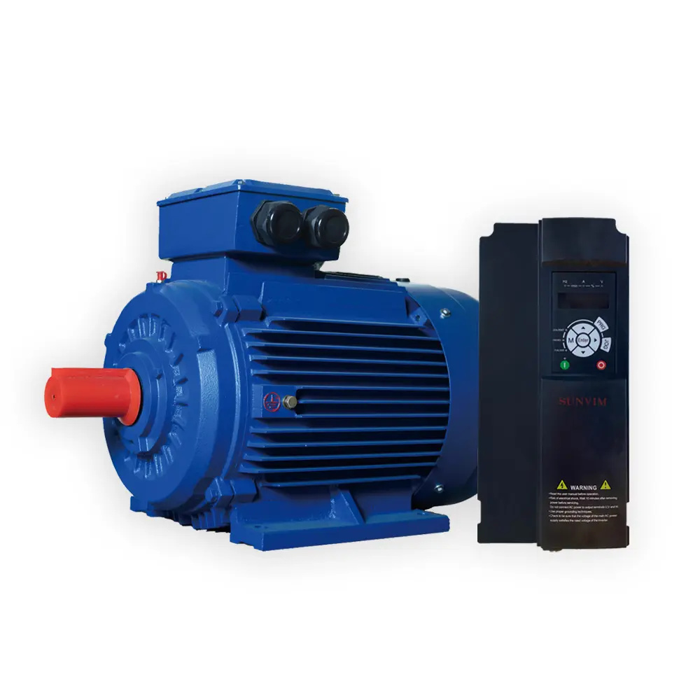
The June 2022 issue of Pumps & Systems published “The Advantages of Synchronous Motors,” an article discussing the expected growth in the use of synchronous motors in the pumping marketplace.
In the November issue, “Synchronous Motor Testing Using MCA Technology, Part 1,” provided a brief overview of the construction and operation of synchronous motors, common faults and how they can be used to adjust a plant’s electrical systems power factor. Part 2 will discuss how motor circuit analysis (MCA) can be used to assess the current condition of these motors, as well identify any developing issues easily and quickly before they become problematic. YE5 Series

Motor Circuit Analysis (MCA) is a motor testing method that quickly and easily identifies developing faults in the coils in both the stator and rotor windings.
MCA uses a series of low voltage alternating current (AC) and direct current (DC) voltages applied to the stator and rotor coils to identify the small changes that occur in the winding insulation as the insulation between the conductors degrades.
MCA can perform incoming inspections on all new and rebuilt motors in less than three minutes using storeroom personnel with minimal training.
The general procedures and guidelines for testing synchronous motors are the same as those for testing and evaluating three-phase squirrel cage AC induction motors. However, a few additional steps and measurements are required if faults are detected. These additional steps are dependent on the type of motor and the location of the fault. For best results, all motors should be tested when new to establish a baseline.
MCA testing has multiple tests available to optimize and streamline the testing and troubleshooting of synchronous motors. These tests are:
1. Static Test: Performs a series of AC and DC tests while the shaft is in a stationary position. The results of these tests are input into a proprietary algorithm to provide a single number that defines the motors condition. This number is the test value static (TVS). Three-phase motors in good condition have symmetry. Any changes in the condition of the stator or rotor insulation, or cracks in the amortisseur windings, will break this symmetry and be reflected in the TVS.
2. Dynamic Test: Generates rotor and stator signatures while the shaft is being smoothly and slowly manually rotated. These signatures are automatically analyzed to evaluate the electrical condition of the rotor and stator circuits in one of three conditions (good, worn or bad). Stator faults indicate developing faults in the stator windings while rotor faults indicate developing faults in the amortisseur windings or shorts in the rotor field coils.
3. Phase Comparison Tests: Performs a series of tests at five frequencies and uses the test frequency that most accurately defines the condition of the stator windings. The following variables are then compared to predetermined guidelines to evaluate the condition of the entire stator windings.
In three-phase motor systems, the coils that make up each phase are the same, and when in new condition, they will respond to the applied low-voltage AC test signals exactly the same. The AC signal exercises the entire winding insulation system. Developing faults of the insulation between conductors will change the response of the coil. Unbalances in the test results of the coils indicate developing faults in the winding insulation. Detailed limits and guidelines have been established to identify developing faults in the winding insulation system.
This is made using specialized Kelvin clips that make accurate resistance measurements of the circuit under test. Resistance unbalance generally indicates loose connections or broken conductors in the circuit.
This indicates the ability of the individual coils to store a magnetic field. The amount of inductance is dependent on the geometry of the coils and the number of turns. There are two types of inductance:
Self Inductance: the creation of a voltage (electromagnetic field [EMF]) in a coil or a conductor when the current flowing through the coil is changing. The magnetic field in the stator coils is mostly self-inductance.
Mutual Inductance: the creation of a magnetic field in a coil or circuit induced by a changing magnetic field from a separate circuit. There are three conditions required to induce a magnetic field: an existing magnetic field, path for current flow (conductor) and relative motion
During startup, mutual inductance is relied on to create a magnetic field on the rotor using the amortisseur windings as the conductor. Relative motion is created by the differential speeds between the magnetic field on the stator and the shaft.
MCA testing injects a low-voltage, purely sinusoidal AC signal to the coils connected between the instrument leads. This is self-inductance.
Mutual inductance is created in the amortisseur windings and the coils wrapped around the pole pieces. The number of amortisseur windings residing under the energized stator coils or coils under test can vary based on rotor position and may create inductance unbalance. This could create an inductance unbalance during testing because of rotor position. This may provide imprecise results in the other measurements. However, these imprecise results can be easily identified and corrected using additional, easy to perform techniques. The small changes that occur in the early stages of the insulation failure will not affect the overall inductance measurements.
The comprehensive opposition to current flow in an AC circuit; ohms law (current = voltage/resistance) is valid for DC circuits. Reactive currents created by the alternating supply voltages oppose the overall current flow, so the overall opposition to current flow in AC circuits is impedance. Z is affected by the DC resistance of the conductors and any capacitive and inductive reactance in the measured circuit, as well as the frequency of the applied voltage.
The time delay between the current and the applied AC signal. As the insulation surrounding the winding conductors degrades, small changes in either the L or C are too small to affect the overall L (inductance), C (capacitance) or Z (impedance) in the circuit, but will affect the time delay between the voltage and current waveforms. Variations in the Fi between phases is an early indication of a developing winding short.
Current frequency response (I/F):
Capacitance and inductance store an electrical charge and a magnetic field respectively. The I/F measures the ability of a coil to store a magnetic field or an electrical charge. When the coils that form the poles and phases in the stator windings are in the same condition, they will store the same electrical charge and magnetic field. Even small changes in a coils L or C affects the ability of the coil to store a magnetic field or an electrical charge. The I/F calculates the ratio of the change in a current from the initial current by doubling the frequency of the applied signal. Variances in a coil’s ability to store either an electrical charge or a magnetic field are early indicators of developing insulation breakdown between conductors in the winding system.
The ground wall insulation is any insulation that separates the energized portion of the motor from the frame or other exposed parts of the motor.
Insulation resistance to ground (IRG)—megaohms:
This measures the weakest part of the GWI. This test ensures there are no weaknesses in the GWI that would allow voltage applied to the winding to energize the motor frame or other parts of the motor. This is a safety measurement and fails to indicate the overall condition of the GWI.
Dissipation factor (DF) and capacitance to ground (CTG):
When combined with IRG, DF and CTG provides a better indication of the overall condition of the ground wall insulation system. DF is the ratio of the resistive current/capacitive current. As a dielectric material degrades or becomes contaminated, the DF will increase, indicating a change in the overall condition of the ground wall insulation. The CTG measurement should remain constant throughout the life of the motor. Contamination causes the CTG to increase, while thermal degradation of the insulating material will cause the CTG to decrease.
All new motors should undergo an MCA static, dynamic and phase comparison test. The results of these tests are stored for comparison of future tests.
Prior to installing a motor, perform a static test and compare to its referenced value static (RVS). If the current TVS is less than 3% of the RVS, the motor’s condition has not changed. Install the motor and perform a new static test from the controller or a local disconnect. All future MCA tests can be performed with a three minute test from the motor control center (MCC) or a local disconnect.
If this value is within 3% of the RVS, the motor is in the same condition. Any static tests that are greater than 3% of the RVS indicate faults have developed in either the rotor or the stator. A simple dynamic test can then be performed to isolate the fault to the rotor or the stator.

YE5 Series William Kruger joined ALL-TEST Pro as the technical manager in 2004. He may be reached at wkruger@alltestpro.com. For more information, visit alltestpro.com.