Add the following snippet to your HTML:
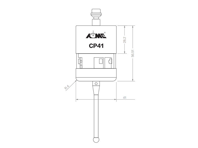
A walk through of how to measure the current with an oscilloscope in WaveForms using a current viewing resistor (CVR). Bench Drill Press
Read up about this project on
A walk through of how to measure the current with an oscilloscope in WaveForms using a current viewing resistor (CVR).
In my previous project post, I walked through how I used the WaveForms image for my Eclypse Z7 to turn it into a USB scope to help prove-in my mini Helmholtz Coil snowglobe by looking at the voltage waveform of it powering up/down and during normal operation on an oscilloscope. I made a note in that project post that I just had to gauge the current draw of the Helmholtz coils based on the current draw shown by my power supply I was using in place of the 3.7v battery I usually used to power the globe.
This was due to the fact that an oscilloscope can only measure voltage relative to time, there isn't a direct way to measure current by just placing a regular probe on a certain point in a circuit. Either an inductive current clamp must be used as it converts the magnetic field generated by the current flow through a wire into a voltage signal, or the current must be measured as the flow through a given device. However, the inputs of an oscilloscope are specifically designed to not allow current flow into it with built in 1MΩ+ resistors in the probes (because that's how lots of magic smoke can be created).
This means that either a device in the target circuit needs to be measured or a device needs to be added to the circuit that doesn't impact the overall function of it. Which is where the current viewing resistor comes into play.
Resistors are the best choice as a tool for measuring an unknown current passing through it since they have a linear frequency response across a broad range of frequencies. In other words their resistance/impedance value remains the same regardless of the frequency of the current signal passing through it, unlike a capacitor or inductor where their impedance value changes in direct correlation to the frequency of the current.
As one might guess, this is why resistors used for this purpose are aptly named Current Viewing Resistors (CVRs). They are also referred to as shunt resistors or current sense resistors. A resistor being used as a CVR is a low resistance value with higher power rating than the rest of the circuit as to:
1) Have minimal impact on the current flow in the circuit as compared to when the CVR is not present.
2) Not risk causing a short that could damage either the circuit itself or the test equipment
Since my target circuit is only 3.7v at 22mA max, a 10Ω 1/4 watt through-hole resistor will work just fine as a CVR here.
Since the resistor has to be a part of the circuit itself, some thought has to go into what specific part of the circuit the current is being measured in. Most commonly, it's done as a measurement at the power supply of the circuit to verify the circuit as a whole is drawing the appropriate amount of current at power on/off and during operation.
So I set up my 10Ω CVR in series on the return side of the power input of the coils using a breadboard. It is import that the CVR is on the return side of the circuit that is connected to the common ground for the whole circuit as to avoid damaging anything and get the most accurate current measurement.
I then stole back channel 1 of the Scope Zmod that I've also been using to measure the analog output of my new DDS module to connect across the resistor.
This is only a small part of what the chaos that is my desk right now...
Open a Scope tab in the WaveForms workspace, and select Measurement from the toolbar. This will open a new table next to the Scope window. Where custom measurements can be specified.
Click Add and select Custom Channel, then add the custom code to divide each voltage sample by the resistive value of the CVR.
There is some default code for calculating the average value of the voltage on the target channel. I simply modified it to divide each sample (which is a voltage value) by the resistor value of my CVR (10Ω) to give me the instantaneous current measurement:
I set the trigger again and powered on the coils to see what the current looked like on power up. Since the coils are basically large inductors (and the current across an inductor can not change quickly) a ramp type waveform was what I was expecting to see.
I also noticed that the current as measured directly as the input of the driver circuit measured higher at 19.3mA - 19.5mA compared to the 17.5mA - 18mA it reads at the output of the power supply. Which reminded me of the fact that the resistance of the wires going from the power supply to a circuit does factor in and offset the current reading at the power supply. It's not a huge offset, but it does make a difference in cases like this where the total current draw is only in the tens of milliamp range.
While I saw a bit of noise, the current stayed at a steady DC 19.3mA - 19.5mA during operation.
I did see a bit of ringing on the power down side of the waveform, but nothing outside of what I'd call normal.
And that's it for my crash course in using a CVR to measure current with an oscilloscope!
Cnc Machine Tools Hackster.io, an Avnet Community © 2024