To revisit this article, visit My Profile, then View saved stories.
To revisit this article, visit My Profile, then View saved stories. Transformer Power Supply
What happens when you put an inductor and a capacitor in a circuit? Something kind of cool---and actually important.
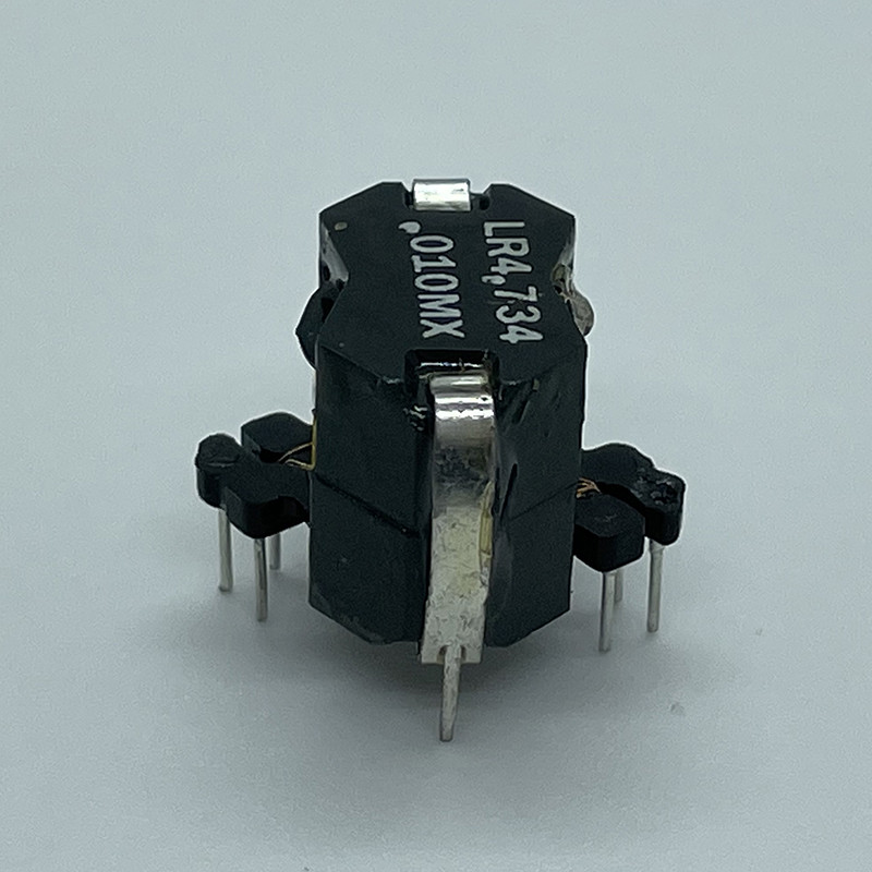
You can make all sorts of different types of inductors, but the most common type is cylindrical coil of wire---a solenoid.
When current runs through the first loop, it creates a magnetic field that passes through the other loops. Magnetic fields don't really do anything unless the the magnitude changes. A changing magnetic field will create an electric field in the other loops. The direction of this electric field will make a change in electric potential that acts like a battery.
In the end, we have a device that has a potential difference that is proportional to the time rate of change of the current (since the current makes the magnetic field). This can be written as:
There are two things to point out in this equation. First, the L is the inductance. It only depends on the geometry of the solenoid (or whatever shape you have) and its value is measured in Henry's. Second, there is the negative sign. This means the change in potential across the inductor opposes the change in current.
How does an inductor behave in a circuit? If you have a constant current, then there is no change (DC current) and thus no potential difference across the inductor---it acts like it's not even there. If there is a high frequency current (AC circuit) then there will be a large potential difference across the inductor.
Again, there are lots of different configurations for a capacitor. The simplest shape uses two parallel conducting plates with electric charge on each plate (but a net charge of zero).
The electric charge on these plates creates an electric field inside the capacitor. Since there is an electric field, there must also be a change in electric potential across the plates. The value of this potential difference depends on the amount of charge. The potential difference across the capacitor can be written as:
Here C is the value of the capacitance in units of Farads---it also only depends on the physical configuration of the device.
If there is a current going into the capacitor, the value of the charge on the plates will change. If there is a constant (or low frequency) current, this current will continue to add charge to plates to increase the electric potential so that over time, this potential will eventually act like an open circuit with the capacitor voltage equal to the battery voltage (or power supply). If you have a high frequency current, the charge will be both added and taken away from the plates in the capacitor with no charge build up and the capacitor will act like it's not even there.
Suppose we start with a charged capacitor and hook it up to an inductor (no resistance in the circuit because I am using perfect physics-wires). Think about the instant right when these two are connected. Suppose there is a switch, then I can draw the following diagrams.
Here's what's happening. First, there is no current (since the switch is open). Once the switch is closed, there can be a current and with no resistance, this current would jump up to infinity. However, this large increase in current means that there will be a change in electric potential produced across the inductor. At some point, the change in potential across the inductor will be greater than that across the capacitor (since the capacitor loses charge with current flow) and then the current will reverse directions and charge the capacitor back up. The process repeats itself---forever since there is no resistance.
It's called an LC circuit because it has an inductor (L) and a capacitor (C)---I guess that's obvious. The change in electric potential around the whole circuit has to be zero (because it's a loop) so that I can write:
Both Q and I are changing with time. There is a connection between Q and I in that the current is the time rate of change that the charge leaves the capacitor.
Now I have a second order differential equation for the charge variable. This isn't such a difficult equation to solve---in fact, I can just guess at a solution.
This is pretty much the same as the solution for a mass on a spring (except in that case it is the position that changes, not the charge). But wait! We don't have to guess a solution, you can also solve this problem with a numerical calculation. Let me start off with the following values:
In order to solve this numerically, I will break the problem into small time steps. During each time step, I will:
Here is this calculation in python (click the play button to run it).
I think that's pretty cool. Even better, you can measure the period of oscillation for this circuit (use your mouse to hover and find values for time) and then compare that to the expected angular frequency using:
Of course you can change some stuff in that program and see what happens---go ahead, you won't permanently break anything.
The above model wasn't realistic. Real circuits (especially the long wires in an inductor) have resistance. If I want to include that resistance in my model, the circuit would look this this:
This will change the voltage loop equation. Now there will also be a term for the potential drop across the resistor.
I can again use the connection between charge and current to get the following differential equation:
With the addition of the resistor, this becomes a much more difficult equation and we can't just "guess" a solution. However, it shouldn't be too difficult to modify our numerical calculation above to solve this problem. Really, the only thing that changes is the line in which the second derivative of the charge is calculated. I have added a term in there to account for the resistance (but not the First Order). Using a resistance of 3 Ohms, I get the following (again, press play to run it).
Here are some things you can try:
Yes, you can also change the values for C and L, but be careful. If they are too low, the frequency will be very high and you will need to change the size of the time step to something smaller.
When you make a model (either analytically or numerically), you sometimes don't really know if it's legitimate or completely bogus. One way to test your model is to make a comparison with real data. Let's do that. Here's my setup.
This is how it works. First, I use the three D-cell batteries to charge up the capacitor. I can tell when it's almost fully charged by looking at the value of the voltage across the capacitor. Next, disconnect the batteries and then close the switch so that the capacitor discharges through the inductor. The resistance is just part of the wires---I don't have a separate resistor.
I tried several different combinations of capacitors and inductors and finally got something to work. For this case I used a 5 μF capacitor and an old crappy looking transformer for my inductor (not shown above). I wasn't sure about the value of the inductance, so I just estimated the angular frequency and used my known value of capacitance to solve for an inductance of 13.6 Henrys. For the resistance, I tried to measure this value with an Ohm meter, but using a value of 715 Ohms in my model seemed to work best.
Here is a plot from both my numerical model and the voltage as measured in the actual circuit (I used a Vernier differential voltage probe to get voltage as a function of time).
It's not a perfect fit---but it's close enough for me. Clearly, I could play around with the parameters a bit to get a better fit but I think this shows that my model isn't crazy.
The key feature of this LRC circuit is that it has some natural frequency that depends on the values of L and C. Suppose I do something a little different. What if I connect an oscillating voltage source to this LRC circuit? In that case the maximum current in the circuit depends on the frequency of the oscillating voltage source. When the voltage source is at the same frequency as the LC circuit, you get the largest current.
Here is where you could use this idea:
The tube with the aluminum foil is a capacitor and the tube with the wrapped wire is an inductor. Together (with a diode and an earpiece) these make a crystal radio. Yes, I put this together with some simple supplies (I followed the instructions on this YouTube video). The basic idea is to adjust the values of both the capacitor and inductor to "tune" to a particular radio station. I couldn't quite get it to work---I think there just aren't any good AM radio stations around (or maybe my inductor sucked). However, I did find this old crystal radio kit that worked a little bit better.
I found one station that I could barely hear, so I think that there's a chance that my homemade radio just wasn't quite good enough to pick up a station. But how exactly does this RLC resonance circuit work and how do you get an audio signal from it? Maybe I will save that for a later post.
Coil Inductor © 2024 Condé Nast. All rights reserved. WIRED may earn a portion of sales from products that are purchased through our site as part of our Affiliate Partnerships with retailers. The material on this site may not be reproduced, distributed, transmitted, cached or otherwise used, except with the prior written permission of Condé Nast. Ad Choices