Editor's note: A long-time industry veteran and expert on scientific molding, John Bozzelli is a processing guru, consultant, and principal of Injection Molding Solutions in Midland, MI. A current trend within the injection molding industry is to use electric rather then hydraulic machines. Word on the street is that for machines in the 30- to 300-ton range, between 50 to 70 percent of all machines sold are electric or hybrid. Why? Reasons include improved accuracy, decreased energy consumption, quieter and cleaner (no oil) operation, and dropping prices. And while electrics are not liked by everyone and do not work for every application, they are becoming more popular, finding niches in a broad range of applications. Chances are you will be making the switch. So if you do become faced with processing a job on an electric, what is different? You knew how to tweak the old faithful hydraulic. But how do you tackle this new electric? Do you have to change your process or process strategy? Let's start with making sure you have the right electric for your job. The Right Machine Regardless of whether you are running an electric, a hybrid, or a hydraulic, there are certain variables that must be considered when choosing and setting up a machine for a specific job. You have to do your homework in terms of tiebar spacing, platen size, footprint, and other general characteristics when buying any machine. Specifications for the machine have to match those required by the molds you intend to run. Do not put small molds in big machines or buy the biggest barrel just to be sure you have enough plastic for almost any mold. Small molds in big machines can crack tiebars due to platen wrap (use at least 70 percent of the surface area between tiebars). Using less than 25 percent of the barrel capacity is asking for polymer degradation due to residence time (dependent on cycle time), and poor shot control. On these issues there's no major difference in requirements between a hydraulic machine and an electric. Clamp tonnage also doesn't present much variation between electrics and hydraulics. Most electrics will be toggles. Hydraulic clamps push on the moving platen in the middle, but with toggle clamps the main force is on the four corners of both platens. If you have been running a hydraulic press and your tool has been hobbed at the parting line, then moving to a toggle clamp may be significantly different. However, if you have a good tool that has not been abused and is in good shape, a toggle can do a nice job. You may still need to add some center preloaded support pillars.
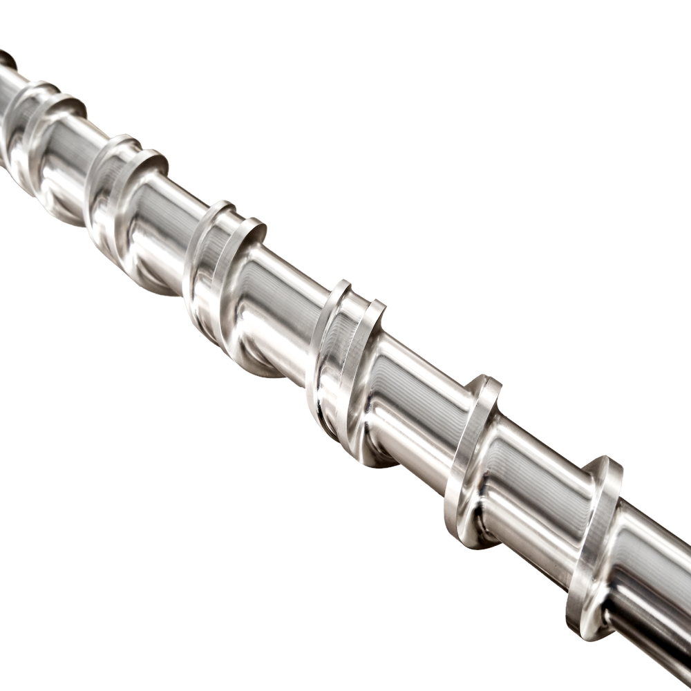
Nozzle contact force, which is generally not an issue with most hydraulics, can be an area of concern on some electrics. With electrics make sure there is enough nozzle contact force. In an electric there is no hydraulic pull-in cylinder to pull the sled forward; it's an electric motor providing the force. When the nozzle is up against the sprue bushing you need tons (2 to 15) of force to keep that seal tight so that plastic does not leak (or blow back) out between the nozzle tip and the sprue bushing. It has to hold 16,000 to 40,000 psi of plastic pressure. Depending on how this is mechanically constructed on the electric machine there may not be adequate nozzle contact pressure. When an electric motor is trying to turn while holding the nozzle tip up against the sprue bushing, there is a concern that the motor might get too hot, so the torque is limited. There are more than a few stories about electrics forming one of those heater-band-killing donuts of plastic around the nozzle body/barrel. Ejection force, which is again not a problem with hydraulics, may need extra attention on an electric. Generally there is plenty of ejection force. The concern is with what stops the ejection mechanism. With hydraulics if you use high ejection force and the ejection stroke is longer than the travel of the ejector plate, you may bend an ejection rod or damage the mold. With an electric machine, if you have high ejection force and the stroke set on the controller is longer than the travel allowed, the drive mechanism might fall out of sync as it tries to push the ejector plate farther than the mold will allow. If it is a belt-drive ejection mechanism, the belt, which is similar to a timing chain, can skip. If this happens, you're looking at a day or two for repairs; on an electric motor direct-drive system it's not good for expensive servos to be overtorqued. Getting Ready to Run OK, the mold is in the press, and you have the clamp set up with the correct opening and closing speeds, correct ejection force, velocity, and stroke distance. The next thing to consider is mold protection. Setting this on an electric is easy and often more sensitive than on most hydraulics. Not only can you set mold protection for the last several millimeters or inches of travel but some electrics can also monitor the pressure to close the clamp for the entire travel distance. Some can be set in such a way that even at fast closing speeds you can drop a foamed polystyrene cup between the faces of the mold and the electric will not crush the cup by more than about 5 mm. With this kind of control and potential mold protection it is important to learn how to set these controls and use them. The next step is getting the shot ready. First on the agenda is melt temperature. To be fair, melt quality and temperature should be matched from machine to machine for the switch. This is not just setting barrel temperatures. Screw rpm and backpressure also must be set correctly. Setting barrel temperatures should be nearly identical provided you are not moving from a severely worn barrel and screw to a new barrel and screw. Any specially designed screw and barrel combination would have to be carried over to the electric. Screw Barrel
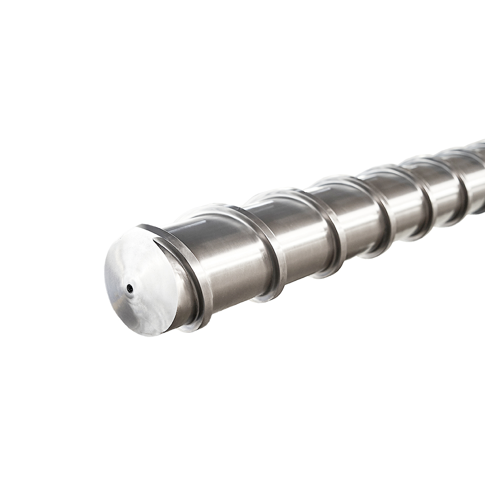
Unfortunately, most molders do not pay enough attention to what state-of the-art screw technology can do for the bottom line. There is some real low-hanging fruit (profit) that can be taken advantage of with newer screw technology with little or no extra capital outlay. The new machine needs a screw anyway, so it might as well be one that works for you and not against you. Standard general purpose screws do not provide melt uniformity and often have trouble blending in concentrates. Still, overall there is little difference between melting plastic in a well-controlled hydraulic vs. an electric. In fact, some hydraulic machines are going back to electric screw drives, which is interesting since electric screw drives were on the first reciprocating screw machines. Screw positioning and suck back may be more accurate because control of inertia on electrics is better than it is on hydraulics. Revolutions per minute (rpms) would be the same for identical screw sizes, but that is rarely the case when you switch machines. My preference is to duplicate the screw rotate time (plasticating time). This involves setting backpressure correctly. Plastic Pressure vs. Hydraulic Pressure Backpressure settings on electric machines may startle a few processors. On hydraulic machines it is popular to use between 50 and 200 psi of hydraulic pressure as backpressure during screw rotate. On electrics the numbers are going to be different by an order of magnitude. To explain this variation we first have to make sure everyone is on the same page as to how backpressure is generated. The metering section of the screw pushing plastic forward generates it, which in turn pushes the screw back. For a hydraulic machine the figure above depicts a rough schematic. As shown in the drawing, a setting of 60 psi on a hydraulic actually requires the screw to push plastic forward at plastic pressures slightly more than 600 psi to push the screw back. As the screw retracts it forces oil out of the hydraulic cylinder through a relief valve and back to the tank. This relationship between hydraulic pressure and plastic pressure is known as the intensification ratio. What is this intensification ratio (I R )? In all hydraulic injection units, hydraulic power is converted or amplified into plastic pressure. The law of physics involved is F = P x A. That is, force (F) is equal to pressure (P) times area (A). The large hydraulic piston acts on the screw, or essentially the nonreturn valve. The hydraulic piston has a large surface area—for example, 100 sq cm. The nonreturn valve during injection forward acts like a smaller area piston—for example, 10 sq cm. This causes the hydraulic pressure to be converted to plastic pressure in the barrel. In this specific case hydraulic pressure is intensified or multiplied by a factor of 10. That means 60 psi of hydraulic pressure provides roughly 600 psi of melt pressure inside the nozzle of the machine. This is called the machine's intensification ratio and explains how hydraulic pressure can provide tens of thousands of psi of plastic pressure inside the nozzle. During second stage, for example, a 1200-psi hold pressure setting (hydraulic) provides 12,000 psi plastic pressure. Today you can buy machines with intensification ratios that range from 6:1 to 43:1. All machines are not 10:1, and rarely are they whole number ratios. It is plastic pressure that pushes plastic into the sprue, runner, gate, and mold cavity, not hydraulic pressure. If your plant has different machines, most likely they have different intensification ratios. It is because of these different ratios that one cannot use the same hydraulic pressure press to press. OK, now that intensification ratio is explained, how do you set backpressure on an electric machine? All electric machines work in plastic pressure, not hydraulic pressure, and most use a pressure transducer behind the screw drive mechanism to measure force directly. First, you have to find the intensification ratio of the hydraulic machine you were using. You can then multiply the backpressure setting you used for your last process by that hydraulic machine's intensification ratio and you will have your backpressure setting for the electric machine. Electrics have a 1:1 intensification ratio and have to be calibrated in plastic pressure. Bottom line: My recommendation is to run with 1000 to 1500 psi plastic backpressure unless you are working with an easily degraded material (such as acetal or PVC) or a vented barrel screw. Processing Values We also have to address machines that do not provide values for setpoints but instead provide percent values. If your machine works on percents, you have an extra calculation and a minor nightmare. You have to take the percent setpoint and multiply it by whatever 100 percent is found to be equal to. Unfortunately, finding what value correlates to 100 percent can be time consuming, painful, and nightmarish. Personally, I would like to take every technical employee and executive of any machine manufacturer that uses percents and refit their cars with speedometers with 0 to 100 percent and see how they like it. With today's computers there is no acceptable reason for a machine controller to be using percents. The computer can easily multiply the percent times the maximum and provide that number in bar or psi, mm/sec, or in/sec. We think in values, so let's use values to set velocities, pressures, shot size, and transfer point. To set shot size and position transfer we will assume the method of molding is to fill the cavity to about 98 percent full on first stage under velocity control and switch over to second stage (pack and hold) via stroke position (position transfer). Assuming the screw diameters between machines are different, the new shot size can be calculated. Take the shot size or length of stroke and the hydraulic machine's screw diameter and calculate the volume of the shot by using the formula for volume of a cylinder (V=pr 2 l, where r is the screw radius and l is the stroke travel). Then solve for l by using the calculated volume and the electric's screw diameter or radius. Shot size settings wind up being no different than if you were moving to another hydraulic machine. Once shot size is set we need to cut off velocity control before we hit the end of the cavity. We must correctly set position transfer. This will often be a change from your old faithful hydraulically driven workhorse. Most hydraulically driven injection units behave differently at position transfer than electrics. For example, if we have a low pressure for second stage, let's say 10 psi hydraulic with a 12.5:1 intensification ratio, then plastic pressure is 125 psi. If we inject at a fast speed, what happens when the screw hits the position transfer setpoint? The screw does not stop. It continues to coast forward and then sometimes bounces back. There is screw overtravel from momentum, something like a boat in water when you cut the throttle. There is no brake on most hydraulic machines. The faster the injection speed the greater the inertia; at slower speeds the less inertia or kinetic energy. However, with electric machines the drive mechanism for injection forward is different. The drive is an electric motor coupled to the screw via some mechanical means, be it a belt or ballscrew. When the motor stops on an electric there is a breaking action that is not found on most hydraulics. The inertia is controlled because of the mechanical link. Each revolution of these drive motors can be broken into 2000 to 8000 segments. Talk about stopping on a dime! This allows precise control of transfer position. What does this mean in terms of changing your process? Often you can push more plastic in during first stage because the inertia will not overtravel the screw. You get more or better control of first stage, especially at fast injection speeds. On some electrics you can even adjust the rate of acceleration to your setpoint velocity in milliseconds. Be careful not to set this acceleration too fast, as it is a common cause for overtorque on servomotors. It is this control over inertia or braking effect that is one of the major advantages of electric machines, yet it is rarely discussed. Remember, to duplicate a process, fill time must be the same between the machines and consistent. So for any switch between any machines adjust the velocity setpoint to duplicate fill times. Now, first stage is done and velocity is controlled to 98 percent full on position switchover. With fill time consistent to +/-.04 second the pressure at transfer becomes important. Both hydraulic and electric machines should report this as it is a measure of viscosity. So if you are watching this number expect it to vary a bit as it adjusts for viscosity differences. It should not be much different between the hydraulic and electric machines when the intensification ratio is factored into the calculation to compare true plastic pressure values. Second-stage Differences As the machine switches from first to second stage the part begins to pack out and we hold injection forward pressure for some accepted amount of time, which depends on whether the gate needs to be sealed or unsealed. For both first and second stages on electric machines the pressure values are plastic pressure, just like the backpressure previously discussed. To switch from the hydraulic machine to an electric the hydraulic pressure values should be converted to plastic pressures via the intensification ratio. There should be little difference in pressures when viewed in plastic pressure values. It may seem strange as the hydraulic values will be 500 to 2500 psi, while the electric machine values will be 5000 to 30,000 psi (plastic pressure). When the second stage calls for high pressures and long hold times there is a concern for electrics, which we discussed earlier in terms of nozzle contact force. For a hydraulic machine, where the injection forward pressure is maintained by the hydraulic system often through a relief valve, there is no excessive strain on the pump(s). However, for electrics, which are driven by electric motors, a situation is created where the motor is trying to turn during a phase when ram travel is minimal. And what happens to an electric motor that is trying to turn (injection forward) and cannot? It gets hot. This is why electrics require fans. Even the manufacturers of electric machines are aware that long pack and hold times at high pressures may be a problem. In fact, at least one of these manufacturers lists on its specification sheet lower maximum second-stage (pack and hold) pressures than what is available on first stage. It also limits the torque on the electric motor to prevent overload and overheating. With our part filled, packed out, and cooling we start screw recovery to build the next shot, suck back if necessary, and wait a second or two before opening the mold. Ejection takes place and we are ready to start the next cycle. So, what are the big differences between hydraulic machines and electrics from a processing perspective? The three primary differences are the need to watch out for hydraulic clamp vs. toggle clamp issues, the requirement of working in plastic pressure vs. hydraulic pressure, and the advantages offered by electrics for more precise control of screw position for filling and shot size. What is interesting is that reading between the lines one can begin to determine the important plastic variables that really belong on a setup sheet. With either hydraulic or electric presses the plastic variables need to be identical to make identical parts.
Medical-grade PBT Resin Suited for Molding Diabetes Device Parts
The Wide World of Plastics at NPE2024
Breaking News in Flexible Packaging May 2024
Screw Of Extruder Copyright © 2024 All rights reserved. Informa Markets, a trading division of Informa PLC.