We use cookies to provide you with a better experience. By continuing to browse the site you are agreeing to our use of cookies in accordance with our Cookie Policy.
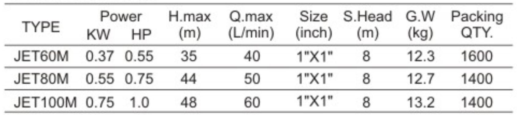
The 2024 International Plumbing Code (IPC) and 2024 Uniform Plumbing Code (UPC) were recently published, and many states are now reviewing the 2024 editions of these codes for adoption. Meanwhile, the deadline for code changes for the 2027 plumbing and mechanical codes for both the international and uniform codes is fast approaching. Smart Hot Water Recirculating Pump
The deadline for code change proposals to the recently published 2024 plumbing and mechanical codes is Jan. 2, 2024, for proposal submissions for the UPC and Uniform Mechanical Code (UMC). Check with the International Association of Plumbing & Mechanical Officials, the publishers of the uniform codes, for the actual due dates.
The proposed code changes for the international codes Group A are due on Jan. 8, 2024; however, please verify the actual due date with the International Code Council on its website.
These codes include the IPC, International Mechanical Code, International Fuel Gas Code, International Property Maintenance Code, International Building Code, International Fire Code, International Private Sewage Disposal Code, International Residential Code (including the residential plumbing and mechanical codes), International Swimming Pool & Spa Code, and International Wildland-Urban Interface Code (IWUIC).
The IWUIC is designed to minimize the effects of wildfires on urban spaces by providing strips of land and building materials that are fire-resistant. This allows very little fuel to burn in a buffer zone between wildlands and urban areas.
In my investigations regarding troubleshooting domestic hot water (DHW) systems, where scalding or Legionnaires’ Disease injuries have occurred, often the hot water temperature maintenance (HWTM) system, through inoperable circulating pumps and problematic balancing valves, contributed to the incident.
Both model plumbing codes include similar language dealing with HWTM systems; this is because, often, the code change proposals are drafted by the same person or organization and submitted to both model code organizations during the same code change cycle.
Each model code organization’s technical committee is allowed to make modifications to the code change proposals, so there may be slight differences from one code to another, but generally, the language and intent of the codes are similar.
For purposes of this column on DHW temperature maintenance systems, I will look at the 2021 International Plumbing Code, which is still adopted and enforced in many areas, and discuss what the code language says about HWTM systems. Note that there will likely be some changes to these sections from the last code cycle and the upcoming code cycle.
The UPC includes similar language; however, for brevity and space requirements, I am not repeating the UPC code sections here. The UPC code sections are available for viewing for free or available for purchase online. My comments generally apply to both codes.
Hot and Cold Water Supply
The 2021 IPC includes the following language:
“At the points of interconnection between the hot and cold water supply piping systems and the individual fixtures, appliances or devices, provisions shall be made to prevent flow between such piping systems.”
My comment: The above language clearly requires the separation of hot and cold water systems and that “provisions shall be made to prevent flow between such piping systems.” These provisions typically include check valves and integral check valves in faucets and fixture fittings, which prevent hot water from crossing over into the cold water piping system or cold water crossing over into the hot water piping system. When crossover occurs, scalding can happen.
In addition, the mixing of hot and cold water can create areas of the piping system where temperatures are ideal for Legionella bacteria growth.
A manufacturer of a small, demand circulation pump came up with a product that intentionally created a cross-connection, where the device pumps previously heated hot water through cold water piping back to the water heater instead of installing a dedicated hot water return pipe. During previous code cycles, the manufacturer touted the benefits of instant hot water, and the proposed code section 607.2.1.2, Demand Recirculation Controls for Distribution Systems, was passed.
This new code section is a direct violation of the prohibition of system interconnections stated in this code section, 604.2. I spoke with a few backflow prevention industry people, and they were mostly not aware of the new section 607.2.1.2. I suspect they might have code change proposals or provide testimony at the upcoming code cycle to address this issue.
“2021 IPC 607.2 Hot or Tempered Water Supply to Fixtures
“The developed length of hot or tempered water piping, from the source of hot water to the fixtures that require hot or tempered water, shall not exceed 50 feet (15 240 mm). Recirculating system piping and heat-traced piping shall be considered to be sources of hot or tempered water.
Group R2, R3 and R4 occupancies that are three stories or less in height above grade plane, the installation of heated water circulation and temperature maintenance systems shall be in accordance with Section R403.5.1 of the International Energy Conservation Code. For other than Group R2, R3 and R4 occupancies that are three stories or less in height above grade plane, the installation of heated water circulation and heat trace systems shall be in accordance with Section C404.6 of the International Energy Conservation Code.”
My comment: The above language established the maximum distance from the water heater or source of hot water to the farthest fixture at 50 feet. This maximum distance used to be 100 feet and was first discussed many years ago in the ASHRAE TC 6.6 before the codes required a maximum distance at which an HWTM system was required.
Over the years, I proposed a 25-foot distance, but this proposal was opposed by homebuilders and their associations because this distance would require many residential hot water systems to include circulation pumps if this language were ever pulled into the residential code. Eventually, the codes compromised on reducing the distance requirement from 100 feet to 50 feet of developed length because that distance would not affect most residences.
I have seen circulated hot water systems and electric heat tracing used to maintain the temperature of the hot water distribution system up to near the fixtures. Both systems have pros and cons.
Hot Water Storage Pump and Demand Recirculation Controls
“2021 IPC 607.2.1.1 Pump Controls for Hot Water Storage Systems
“The controls on pumps that circulate water between a water heater and a storage tank for heated water shall limit operation of the pump from heating cycle startup to not greater than [five] minutes after the end of the cycle.”
My comment: The above language only addresses circulator pumps moving water between water heaters and large storage tanks. It does not address circulating pumps serving the hot water distribution system.
When an atmospheric storage type water heater burner is off, cool combustion air drafts upward through the water heater and to the draft hood, making the water heater act as a water cooler. When a copper fin-tube-type water heater burner is off, the fin tubes transfer heat either way, so copper fin-tube water heaters can also be water coolers if the pumps were to run continuously.
In larger commercial buildings, typically two or more water heaters are manifolded to a large storage tank to allow some redundancy for water heating. This code section requires the circulating pump for each water heater to shut off within five minutes. This is generally a function of the water heater control cabinet, where there are contacts for the circulating pump power controls.
Typically, an aquastat is mounted in the hot water storage tank, sending a signal to the burner in the water heater to turn on when the temperature drops and off when the temperature in the hot water tank rises. The dedicated circulating pump for each water heater pumping to a remote storage tank needs to have the pump interlocked to operate the pump with the water heater burner.
This allows the controls to shut off the circulating pump when the burner is off. In addition, it prevents energy loss or cooling of the storage tank when the water heater burner or electrical heating element power or heat pump water heater is off.
“2021 IPC 607.2.1.2 Demand Recirculation Controls for Distribution Systems
“A water distribution system having one or more recirculation pumps that pump water from a heated water supply pipe back to the heated water source through a cold water supply pipe shall be a demand recirculation water system. Pumps shall have controls that comply with both of the following:
“The control shall start the pump upon receiving a signal from the action of a user of a fixture or appliance, sensing the presence of a user of a fixture, or sensing the flow of hot or tempered water to a fixture fitting or appliance.
“The control shall limit the temperature of the water entering the cold water piping to [104 F] ([40 C]).”
My comment: A manufacturer of a small circulation pump came up with a retrofit idea to save installing a dedicated hot water return pipe to a water heater in a typical residence. The above language was proposed and promoted as a water-saving idea, which gained lots of acceptance. However, this code section directly violates IPC 604.2 System Interconnection.
Using demand circulation controls is a Band-Aid approach to address an improperly designed and installed plumbing system. It’s a jerry-rigged piping approach by circulating previously heated water back to the water heater through the cold water distribution piping. The temperature limit of 104 F is only met if the thermal shut-off device is working properly.
If the thermal shut-off is not installed or is bypassed, then the full hot water temperature will be in the cold water piping system, and the potential for scalding hot water flowing from both sides of a shower valve is created, exposing a bather to a potential scalding scenario. Where these devices are allowed to be installed, consumers will be exposed to cold water with dissolved metals from the magnesium or aluminum anode rods in the water heater, and the use of this water to cook or brush teeth poses a health threat.
These devices can affect the functioning of maximum temperature limit stops in showers or bathtub-showers, where adjustments are based on a lower (ex: 45 F) cold water temperature, but 104 F hot water is intermittently circulated through the cold water piping. The maximum temperature limit stop adjustment will not be correct.
Stacking can occur when a water heater has no continuous circulation, allowing the outlet temperature from a storage-type water heater to rise to 30 F above the thermostat set point. When a water heater thermostat is set at 120 F and stacking occurs, the result is a hot water temperature up to 150 F, and when these devices are installed, there can be a cold water temperature up to 104 F.
When these temperatures mix, the maximum temperature of the shower or tub-shower valve can reach as high as 135 F, even when the limit stop was properly set to a much lower temperature when cold water was present (when the shower valve limit-stop adjustment is before the proximity sensor sends hot water into the cold-water pipe).
Demand circulation through cold water piping is jerry-rigging at best and a dangerous health and safety issue at worst, posing as a water and energy conservation effort. Demand circulation was put into the code to avoid installing a properly designed DHW recirculation piping system to maintain hot water at remote fixtures.
It is a dangerous practice exposing consumers to injury (that naturally includes liability for building owners and others) from scalds, Legionnaires’ Disease and other waterborne bacterial infections. In addition, injury to health can occur from dissolved metals in the hot water tank being pumped into the cold water system — in violation of the language in section 604.2 System Interconnection of the 2021 IPC.
All recirculation systems should be properly designed and balanced through a dedicated hot water return piping system, not through the cold water piping system.
I have been designing, investigating and troubleshooting DHW systems for more than 45 years, and I will share some of the things I learned over the years related to HWTM systems.
1. What is hot water temperature maintenance?
Hot water temperature maintenance is the system used to maintain the temperature within the prescribed distance noted in the code (the new codes say 50 feet; some of the older codes say 100 feet).
There are two types of HWTM systems:
• Circulating pump with balancing valves. Hot water circulates from the farthest branches of a large hot water system back to the cold water inlet on the water heater or external storage tank.
• Self-regulating heat trace system. Uses a series of electric heating cables installed along the hot water piping to replace standby losses. Includes HWTM cables, proper insulation type and thickness, and ground fault-protected power circuits.
2. Energy conservation vs. health and safety
The energy code requires a device to shut off recirculating pumps to save energy during periods of nonuse, but the American Society of Heating, Refrigerating and Air-Conditioning Engineers (ASHRAE), along with experienced design professionals, recommend against shutting off circulating pumps for health and safety reasons, including hot water scalds and bacteria growth issues.
When circulating pumps are shut off, the temperatures fall into the ideal temperature range for Legionella bacteria growth; switching the pump on and off creates a significant temperature variation in the hot water system that can lead to thermal shock and scald injuries.
Between energy conservation or health and safety issues, health and safety issues always supersede energy and water conservation. Saving a little water is not more important than killing or injuring someone from the temperature fluctuations that have led to scald injuries and deaths or Legionnaires’ Disease injuries and deaths.
3. How hot is too hot?
Over the years, I have participated in or served on nearly every hot water temperature control standard committee in the United States and Canada. I have served on many plumbing code ad hoc committees dealing with hot water temperatures in the codes, the scald awareness committee with the America Society of Sanitary Engineering, and hot water design committees such as the ASHRAE TC 6.6 Service Water Heating.
In all these committees, discussions came up about hot water usage temperatures and maximum allowable hot water temperatures for the codes and for various temperature control product standards dealing with scald prevention. In every case, each committee looked at the data from the Harvard burn studies and the data showed that when the water gets above 120 F (49 C), the time to receive a serious burn injury drops exponentially.
Based upon this information, these committees agreed that 120 F is the maximum safe hot water temperature to allow someone to get out of harm’s way before a serious irreversible burn injury occurs. The U.S. Consumer Product Safety Commission (CPSC) Bulletin No. 34 was published by the Engineering and Sciences Division of the CPSC. It compiled the time-temperature burn chart in Chart 1, based on the 1946 Harvard Medical College studies of Dr. Moritz and Dr. Henriques under a Department of Defense contract.
The chart was developed by CPSC’s Peter L. Armstrong on Sept. 15, 1978, displaying a few select exposure times under circumstances of full immersion, resulting in superficial, partial or full-thickness scald burns at various water temperatures. I added the 120 F row and filled in the fractions of a minute and the seconds to receive a burn in other areas, as noted.
4. Circulated hot water systems for temperature maintenance
Circulating pumps are the most popular way to move hot water out to the end of a hot water distribution system and then circulate the water back in a dedicated return piping system. In larger buildings with multiple branches and risers of different lengths, the friction loss and flow through each branch can be different. This causes a natural tendency for the hot water to circulate through the path of least resistance, which is the closer branches.
To ensure circulation to branches and risers further away from the water heater, balancing valves are often used to restrict flow in the closer branches and force flow out to the farther branches. In the past, manual balancing valves were installed, which proved to be very difficult and time-consuming for contractors to get a balanced flow to all the branches in larger buildings.
Newer technologies came about with balancing valves, allowing a differential pressure across an adjustable orifice to set flow using a chart. Then, spring-loaded flow balancing valves restricted flow with a graduated orifice slot in the valve port that would open wider as the pressure dropped and would close down to restrict flow as the pressure increased. These pressure-type balancing valves balanced the flow based on pressure and allowed some adjustment for fine-tuning flows to maintain temperatures, but still required some skill and a fair amount of time.
In the last couple of decades, thermostatic balancing valves arrived on the scene. They work by opening and closing to allow flow by sensing the temperature, not pressure. Thermostatic balancing valves did a really good job of providing flow and hot water to all areas of the hot water distribution system. With these valves, a pressure relief bypass or a variable-speed circulator may be needed to prevent a dead-head situation with the circulating pumps.
The farthest branch should always be wide open to allow some flow in the circulation system. Thermostatic balancing valves typically close on the closer branches as the temperature comes up, forcing hot water to farther branches and providing balanced flow and even temperatures.
Next month, we will discuss some issues with circulating pumps, flow velocity, limitations of circulated systems and piping flow diagram options for circulated systems when we discuss commissioning and troubleshooting hot water circulation systems.
5. Electric heating cable temperature maintenance issues
Electric heating cables have been around for several decades. They use electric resistance-heating cables that are available in different temperature ranges. Heating cables can be used as freeze protection or to provide heat for tempered water to hot water. Different cable options have different watts per linear foot to maintain a given temperature for a DHW system.
These systems generally require a little more attention to the overall installation. The insulation contractor is responsible for installing the correct type and thickness of insulation as required by the heating cable manufacturer to resist heat loss and maintain temperature. He also must cover the pipe and the electric heating cable without cutting the electric cables with the insulation knife.
An electrical contractor is responsible for installing the power supply circuits, including a ground fault circuit breaker, since the heating cables are on a water pipe that can leak. The electrical contractor must fasten the electric heating cables to the pipes properly and on the correct pipe and areas as needed. This requires a little more coordination between trades and an added cost for electric circuits, wiring, energy usage and installation.
Yc Capacitor Start Induction Motor Next month, we will discuss some issues with electric heating cables when we discuss commissioning and troubleshooting electric heat traces used for hot water temperature maintenance systems.